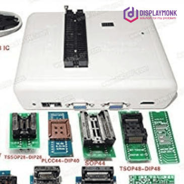
• Skip to primary navigation
  • Skip to main content
  • Skip to primary sidebar
  • Skip to footer

DisplayMonk

Solution to your problem

  • Home
    • Privacy Policy
  • About Us
  • Repair Tips
  • Schematics Bios
  • Course
  • Online Jobs
  • Tools
  • Enquiry / Contact
Home » laptop desktop chip level repair help guide » Page 4

laptop desktop chip level repair help guide

Free schematics bios boardviews

May 15, 2023 by displaymonk

free schematics bios boardviews

Schematics Bios Boardviews for all latest and old laptops and desktops.

Free schematics bios boardviews

Which brand’s schematics are available

We offer brands like Hp Dell Lenovo Samsung Apple Asus Acer Sony Msi Avita Hcl Toshiba laptops and desktop schematics bios and boardview free of cost from the below button. you can use the motherboard code to search for download free schematics bios board views by clicking the below button.

Download Free Schematics Bios Boardview

Thank you for your visit.

Filed Under: laptop desktop chip level repair help guide Tagged With: diagram of laptop, laptop diagram, laptop motherboard diagram, laptop schematics, laptop-schematics, motherboard schematic diagram, tablet motherboard diagram

Quanta Motherboard SIO Requirements

April 17, 2023 by displaymonk

Quanta motherboard sio io signals list

SIO Requirements Supplies in Quanta Motherboards are given below –

Quanta motherboard sio io signals list

1. VCC

This 3v wake up supply on any one VCC pin.

2. AVCC

This is Analog VCC Supply Signal . It is important signal without which analog circuit don’t work in I/O.

3. GND, AGND

It is ground beep signal. Also it have analog ground signal which gives ‘beep’ on the multimeter.

4. 3920_RST#

In Quanta motherboard EC_RST digital signal signal motly given by this name.

5. ACIN

It is similar and same as ACOK signal in Quanta motherboard. This signal get’s generated in Charging IC and then it come to SIO in form of ACIN signal.

6. LID_EC#

This is name for Lid Switch signal in Quanta motherboard.

7. Signal Miss Sometimes in Quanta Motherboard

There is Thermal Signal is missing in Quanta Motherboard. SIO I/O works with very small components to inform CPU.

8. BIOS_RD#, BIOS_WR#, BIOS_CS#

This signals are connected with BIOS. The connectivity is responsible for enabling sometimes step down enable.

9. S5_ON

In Quanta motherboard S5_ON signal is the step down IC’s Enable signal name.

10. NBSWON1#

This power button siganl in Quanta motherboard . It stans for NoteBoomSwitchOn signal. It comes 3V before power button press, 0V when power button pressed and 3V after released the power button. Here the High-Low-High concept for power sequence is created.

11. RSMRST#

This is the first output signal generated by I/O.

12. DNBSWON#1

This is the power button out signal in Quanta motehrboard. It stands for DelayNorthBoardSwitchON.

13. Signal Miss Sometimes in Quanta Motherboard

Sometimes Lid Switchout Signal is Missing in Quanta motehrboard’s SIO I/O.

14. SUSB#, SUSC#

WHen SIO I/O gives RSMRST and PWRBRNOUT signas to PCH, The PCH gives 2 to 3 signals to I/O. These signals are PM_SLP_S3, PM_SLP_S4. In perticulary in Quanta motherboard they named as SUSB# and SUSC#.

SUSB# signal = SLP_S3# signal and SUSC# signal = SLP_S4# signal.

These are the basic requirements for no power on condition in computer and laptop. If these signals come then we can say that our computer or laptop is turn on.

If the laptop is not starting even if these signals coming then we can say that our desktop or laptop motherboard is gone into no display case similar to desktop.

Conclusion

In this we have explained what signal names you should get in Quanta motherboard’s SIO. If you see in the Compal SIO I/I signals, you will have different signals.

We also have basic requirement for general SIO I/O where you get to see the basic requirement for SIO I/O. If not seen please visit and get knowledge expanded.

Above demo is for quanta SIO name quanta_r33_r1a.

You can use the page numbers to go directly to a page where the diagram is. Beware there can be a difference of 1-2 pages in sequence in the diagram we see.

Thank You!

Filed Under: laptop desktop chip level repair help guide Tagged With: 3920_RST#, ACIN, AGND, AVCC, BIOS_CS#, BIOS_RD#, BIOS_WR#, DNBSWON#1, GND, LID_EC#, NBSWON1#, Quanta motherboard's SIO requirement, RSMRST#, S5_ON, SUSB#, SUSC#, VCC

Wistron Motherboard Nuvoton SIO Basic Requirement

April 16, 2023 by displaymonk

wistron motherboard nuvoton sio io signals list

We are going to see Nuvoton SIO’s Basic Requirement in Wistron Motherboard. Wistron motherboard mostly uses Nuvoton SIO IO.

SIO Supply –

Wistron motherboard Nuvoton SIO IO signals names:

  1. VCC
  2. AVCC
  3. VDD
  4. EXT_RST#
  5. PSL_IN1#, PSL_IN2#
  6. LID_CLOSE#
  7. VD_IN1,VD_OUT1#
  8. PSL_IN2#
  9. RSMRST#_KBC
  10. PM_PWRBTN#
  11. PM_SLP_S3#, PM_SLP_S4#

We are going to see them one by one with a description

1. VCC

This is wake up signal for SIO. We see 3v on any 1 pin which is written VCC.

2. AVCC

This is 3v Analog VCC Supply.

3. VDD

This 3v signal comes after the laptop power button presses.

4. EXT_RST#

This is EC_RST# signal for the Wistron motherboard having Nuvoton SIO IO. This gives a 3.3v signal.

5. PSL_IN1#, PSL_IN2#

AC_OK# signal comes here with 0b. If it is written like AC_OK without hash then 3v signal comes. Likewise, if AC_IN# comes then 0v, if SC_IN is without hash then 3v. Power_button signal also comes within PSL_IN1# and PSL_IN2#.

6. VD_IN1, VD_OUT1#

These are thermal signals for SIO in Nuvotone SIO.

7. PSL_IN2#

This signal is the power_button signal. It comes with 3v as default when the power button is pressed it comes 0v when the power button releases it comes 0v.

8. RSMRST#_KBC

It is the RSMReset signal in the Wistron motherboard. This 3v signal goes to PCH.

9. PM_PWRBTN#

PM stands for Power Management. It is PCH’s power management. It is a power button output signal in the Wistron motherboard Nuvoton sio io.

10. Signal Missed

Here Lid Switch signal is missing sometime in Winstron motherboards Nuvotone sio io ic. DY means ‘dead end’ in schematics and there is no further component is present.

11. PM_SLP_S3#, PM_SLP_S4#

This signal comes from PCH to Programmable or Non Programmable SIO IO Chip. PM means Power management here.

Thank you.

Filed Under: laptop desktop chip level repair help guide Tagged With: AVCC, EXT_RST#, LID_CLOSE#, PM_PWRBTN#, PM_SLP_S3#, PM_SLP_S4#, PSL_IN1#, PSL_IN2#, RSTRST#_KBC, SIO IO requirements, VCC, VD_IN1, VD_OUT1#, VDD, wistron motherboard nuvoton sio io signal

Compal Motherboard SIO IO requirements supply names

April 11, 2023 by displaymonk

Compal Motherboard SIO Signals

KB9012QF is a programmable IO which means the BIOS is present within it. There is a list of programmable SIO provided. So we are going to see Compal Motherboard SIO IO requirements supply names

Supplies for Compal Motherboard IO / SIO

  1. EC_VDD/VCC
  2. EC_VDD/AVCC
  3. EC_RST#
  4. ACIN
  5. LID_SW#
  6. VCIN_PH, VCOUT1_PH, VCOUT0_PH#
  7. EC_SPI_MISS1, EC_SPI_MIS_1, EC_SPI_CLR_R, EC_SPI_CS0#
  8. EC_ON
  9. ON/OFFBTN#
  10. EC_RSMRST
  11. PBTN_OUT#
  12. EC_LID_OUT#
  13. SIO_SLP_S4#, SIO_SLP_S5#, SIO_SLP_S3#

We are going to see them one by one with a description

1. VCC

VCC is also called as Digital VCC.

2. AVCC

AVCC is an analog signal which is also called a wake up signal.

3. EC_RST#

EC_RST# is a EC Reset signal.

4. ACIN

ACIN which is also ACOK signal which comes from charging IC.

5. LID_SW#

It is a LID Switch signal also it will come 0volt if problem with this signal.

6. VCIN_PH, VCOUT1_PH, VCOUT0_PH#

They are thermal pin signals which mean related to thermal pins. When PH comes in the signal it means thermal pin.

7. EC_SPI_MISS1, EC_SPI_MIS_1, EC_SPI_CLR_R, EC_SPI_CS0#

These are data pins also, specially when BIOS is present inside the SIO then we can’t check BIOS pins. We can check whether correct data is coming via DSO.

8. EC_ON

This enables pin of source for 3v 5v step down section ic.

AFTER PRESSING POWER BUTTON

9. ON/OFFBTN#

3v is present there and when we press the power button it goes to 0v and when we release the power button it comes to 3v.

10. EC_RSMRST

3v comes in this signal before the power button is pressed in some motherboards and in some motherboards after pressing the power button.

11. PBTN_OUT#

It gives a 3v output after the power button is released.

12. EC_LID_OUT#

From this 3v goes to PCH or SOC in modern laptops.

13. SIO_SLP_S4#, SIO_SLP_S5#, SIO_SLP_S3#

There also comes S5 and S0 signal if it presents in the schematic.

Filed Under: laptop desktop chip level repair help guide

Most Common Laptop Problems and How to Repair Them

April 7, 2023 by displaymonk

Most Common Motherboard Problems and Solutions for Laptop Motherboard Chip Level Repairing with Multimeter

The flow starts from the VIN pin which injects voltage into the laptop. The voltage at this point may vary from 18 volts to 20 volts. There are different laptop SMD and Non-SMD components present on the schematics. We are going to see the most common problems in depth to solve them.

Checking the problem by the Symptom:

Service log is made by technicians to make a record of faulty motherboard electricity and signal system , every single voltage and signal measurement are notice in this log.To narrow the search of missing voltage and signal.

3v -5v system in laptop chip level repair motherboard

Dead motherboard:

no led indicator at all, no fan moving ,no power .This mother board require an adapter voltage (12V_15V_16V_18.5V_19V_20V) also 3V and 5V to completely VALW power supply need. without this impossible motherboard to a life.

Starting with checking power jack to ensure adapter continuity supply P channel mosfet transistor ended to P channel mosfet transistor for battery fet.This line power contribution called Main circuit line of VALW power supply.Open schematic (ensure match motherboard and schematic code)for charger IC page and trace started from DC jack to adp P channel mosfet (or same motherboard using Inductor or Diodes to replace transistor on circuit) make sure continuity supply for charger IC VCC,DC/DC main supply IC VCC and each Upper N channel SOURCE to produced 3V and 5VALW.Signal confirmation EC Bios working name is RSMRST# for 3.3V

No display motherboard:

led indicator on, switch on but no internal or external display.There are 3 boot strap device supported to make motherboard load to display of course after Bios system working properly

Processor:

Without this motherboard will not be able to display. power name by VCCORE and enable signal called VR_ON or V_RON as a trigger from Embedded controler(EC) to enable or disable VCCORE IC. Processor need power supply greater than 1.05V but some AMD processor only need power greater than 0.9V.

SODIM:

Sodim power called VCCRAM.There are 2 VCCRAM need to make sodim working :1.5V and 0.9VTT for DDRIII and 1.8V_0,75VTT for DDRII. There are different components like capacitors, diodes, resistors, crystals, coils (aka inductors), transformers, transistors, MOSFETs.

CHIP’s(SB/NB/VGA):

Chip Power is called VCCP. There are very complex power supply systems. Chip need 19VALW-5/3VALW-5/3VS-1.2VS- 1.05VS.Chip also has they own RAM and need a power supply to work. Signal confirmation chip was ok on chip PWRGOOD for 3.3V or tolerance 10%
Note every missing power and replace damaged component. 3.Power Drop:
Led Indicator on , switching on, on for a few seconds after that
back off. This symptom happens because power spike or there is shortage on VS line. Processor and Chip are most which can cause power spike, look at VCORE and VCCP circuit line
, the circuit has provided a stockpile empty pad to add some more capacitors to anticipate power spike during boot up process. The other problem of the power drop are some shorted on VS line ,so after switch on VS active 1 or more VS line got a feed back caused power down and shutdown the system.

valw supply shorted

The adapter led Blinking or drop, the Current high Voltage down, and no movement at all(Dead shorted motherboard).This feedback comes from VALW main power supply line. Checking this by tracing any sorted component on VIN and VBAT+line. Finding shorted by checking all components having Cathode and anode.

No switch/Can not Switch on:

There are few system switch found for different circuit manufacture, measuring switch voltage on one of switch button pin, before switch standby power available for 17~19V comes from 51_ON#and after switch on power switching vcc 3.3V replace 51_ON# supply than EC_ON# one of pin Embedded controller reacted for on/off mode.

Switching system shorted power switch to the ground, while shorted vcc become zero volt than 3.3V_vcc replace 51_ON# 17- 19V become 3.3V.this signal read by Embedded controller to switch on or switch off the system. The other system used 3 or 5V switch button VCC. when 3or5V shorted to the ground by switching button ,3V will drop to zero volt(for 1 second) EC will reacted to power on the system and when 3or5V shorted for more than 3 second ,EC will reacted to power off the system.

How to Check No Display Problem on Circuit Procedure

a.Check device : processor , memory / SODIM , webcam , modem , wifi , card reader etc.

b.processor/SODIM tested , SWITCH on again .

c. physical analysis components : memory sockets loose , component crashes , burns , cracked , broken or any form of physical damage .(Make a replacement if any)

check procesor vccore voltage ( schema apply ) INDUCTACE ( R36 , R45 , R56 ) / capacitor ( 330uf – 220uF – Tokin NEC super capacitor ) range 1.0VS~1.5VS to normal operate.
example ic / chip For cpu power is : ( VCCORE / CORE CPU / CPU DC / POWER processors )
Example Vccore IC/VRM controller :
(ADP3166 ADP3170 ADP3421 AIC1567 CS5322 FAN5056 ITC1709 MAX1710/MAX1711/MAXl712 HIP6004 , ADP3212’MAX8760 , MAX8770 , MAX8771 , ISL6260 , ISL6265A , ISL6266A , ISL62882 , ISL6262A,ISL6218CV – T , ISL6269CCR .. etc )

receiving and sending signals for sio aka io in every laptop chip level repair

check for memory and power voltage conductors and ground socket interface memory. VCCRAM normal operational voltage
1.8 V and 0.9VTT for (DDRII) and 1.5V/0,9VTT for (DDR3)

examples of memory / power SODIM ( schema languages : VDDR / POWER MEMORY / VTERM / DDR PWR ) ic examples : (MAX8794 NCP5201 SC1486/SCl486A SC2616 TPS51020 ISL6520 ISL6537 CM8501 , ISL6224 ISL6225 , TPS51116EGR , RT8207A … etc ) .

Check voltage on S.I.O /EMBEDDED CONTROLLER chip:

S.I.O managed a lot of signal, start from pwr button signal, switching VALW to VS power and steeping process signal sleep state. We can detected normal ic and firmware bios from confirmation signal of RSMRST#3.3V .If SPI setting, IC bios and firmware not working, this S.I.O will not working. This S.I.O programme by microcontroler .(download example S.I.O datasheet to get more information)
S.I.O chip samples are :
(WINBON/ENE/ITC/NOUVOTON/ PC97338 , PC87392 , FDC7N869 , FDC37N958 , LPC47N227 , LPC47N267 PC87591S
/ PC 87591L / PC 97317IBW/PC 87 393 VGJ PC87591E , WPC8768L , KB926D etc ) .

Check voltage and ground at the thermal sensor IC

Thermal sensors ( heat sensor ) is a sensor chip that detects heat safe limits to maintain security motherboard chips. almost all laptops have a thermal sensor to microprocessor and some motherboards have a thermal Graphic chip to chip .Thermal sensor will give orders to the bios if it detects a maximum heat limit to disconnect power to the processor or VGA or just turn off bootstrapping ( command to boot ) and stop the interface between components that aims to keep the excessive heat damage the chip ( protect error ) .

Detect due to frequent excessive heat can cause thermal sensor or faulty memory detection and sensor commands do not get along (False alarm). Thus the chip detects heat temperature maximum continuous conditions, although they are not.
To reconcile the sensor detection is by lifting the chip from the motherboard and put back to give the induction . if the sensor is already damaged and could not be reset we will have to replace the sensor chip that is still accurate .

ic examples :
ADMI032 , EMC1402 , EMC4402 , EMC4401 , GMT781 , G768B , MAX6642 , MAX6657 , SMC1423 .. etc

Check voltage or frequency of the clock generator: sample clock generator chip :

ALPRS355B MLF64PIN, CK505, CK408, K410M, CY2854LVX , ICS9LPRS387 , ICS9LPR600
ICS951412 , ICS954213 , ICS9LPR363DGLF – T , ICS950810 , SLG8SP626 , SLG8SP513V , SLG8LP465VTR,SLG8SP553V , SLG8LP55VTR , SLG8SP513VTR … etc.

a.Check Chip power
b.Check chip signal and state trigger.

c.Check Bios microcontroller system(including check for S.I.O or embedded controler)
d.SB/NB/Chip analyses .
e Reflow~reball~replace the chip . ( Fixing ball lead / tin loose chip due to heat )
note : Chip -level is not described in detail on the basis of the material .
sample chips :
SB/NB/ CHIP : – ( PC97338, PC87392, FDC7N869, FDC37N958, LPC47N227, LPC47N267 PC87591S / PC 87591L / PC 97317IBW/PC 87 393 VGJ PC87591E etc ).

Laptop Troubleshooting – Symptoms of PCH CPU and SIO Failure!

For any computer to work properly, there are several circuits and microchips that must cooperate on the motherboard. These include the all-important processing unit (CPU), the Platform Controller Hub (PCH) and the Serial Input/Output (SIO). All these units have individual functions that collaborate to make one interconnected system.
How the CPU, PCH, and SIO Work Together in a Laptop Motherboard
The PCH (Platform Controller Hub) can be referred to as a family or set of Intel Microchips. As the name suggests, the PCH controls various data paths and functions that work with the Central Processing Unit.
The SIO, on the other hand, is an integrated circuit located on a computer’s motherboard that handles the slower, less demanding input/output devices. In conjunction with the CPU and the PCH, the Serial Input/Output has control over floppy disk controller, infrared, parallel ports, serial ports(DB9) and mouse as well as temperature and fan speed in your computer.

Symptoms of Damaged or Failing PCH, CPU, and SIO

–Computer turns on without any display or sound.
-Computer fans run at much higher speeds even when computer is idle
-Operating system freezes unexpectedly
-temperature rises unusually/suddenlly
-All serial and parallel ports do not work
-Frequent, unexpected system shut down

Graphics Brands : –

ATI , NVIDIA , S3 , NEOMAGIC , TRIDENT , SMI ,
INTEL , FW82807 , and CH7001A , etc. .

There are few system switch found for different circuit
manufacture. measuring switch voltage on one of switch button
pin, before switch standby power available for 17~19V comes
from 51_ON#and after switch on power switching (VSB) 3.3V
replace 51_ON# supply than EC_ON# one of pin Embedded
controller reacted for on/off mode. Switching system shorted
power switch to the ground, while shorted VSB (Voltage Switch
Button) become zero volt.


First reset signal on computer circuit

RSMRST#
When the Power, Bios,Ec are OK, the RSMRST# will go high. In
the other word, this pin go Low only when the system reset.If
BIOSdata is error, RSMRST# won’t go high.

Here PCH(platform controller host) is the combination of north
and south bridge.
Laptop Troubleshooting – Symptoms of PCH CPU and SIO
Failure!
For any computer to work properly, there are several
circuits and microchips that must cooperate on the motherboard.
These include the all-important processing unit (CPU), the
Platform Controller Hub (PCH) and the Serial Input/Output
(SIO). All these units have individual functions that collaborate
to make one interconnected system.
How the CPU, PCH, and SIO Work Together in a Laptop
Motherboard
The PCH (Platform Controller Hub) can be referred to as a
family or set of Intel Microchips. As the name suggests, the PCH
controls various data paths and functions that work with the
Central Processing Unit.
The SIO, on the other hand, is an integrated circuit located on a
computer’s motherboard that handles the slower, less demanding
input/output devices. In conjunction with the CPU and the PCH,
the Serial Input/Output has control over floppy disk controller,
infrared, parallel ports, serial ports(DB9) and mouse as well as
temperature and fan speed in your computer.


Symptoms of Damaged or Failing PCH, CPU, and SIO

–Computer turns on without any display or sound.
-Computer fans run at much higher speeds even when computer
is idle
-Operating system freezes unexpectedly
-temperature rises unusually/suddenlly
-All serial and parallel ports do not work
-Frequent, unexpected system shut down

Filed Under: laptop desktop chip level repair help guide

dell beeping sound on startup how to troubleshoot

March 13, 2023 by displaymonk

dell sound of beeping on startup

Introduction

When a Dell laptop or desktop beeps during startup, it is usually an indication of a hardware problem. There problem may come like

  • 3 beep sound in dell laptop,
  • 4 beep sound in dell laptop,
  • 5 beep sound in dell laptop,
  • 7 beep sound in dell laptop,
  • beep sound related to cpu,
  • dell 2 beep code,
  • dell 3 beep code,
  • dell 4 beep code,
  • dell 5 beep code,
  • dell deffrent beep codes,
  • dell beeping sound on startup

dell laptop gets beeps on startup solutions:

Here are a few common causes of beeps during startup for Dell laptops:

RAM problem:

If the beeps are continuous and repetitive, it could be a problem with the RAM. This could be due to a loose connection, faulty RAM module or incorrect installation of RAM.

Overheating

If the laptop overheats, it can cause beeping during startup. This is because the laptop’s BIOS has a temperature threshold that, when reached, causes the system to emit an alarm.

Motherboard failure

A beep code may indicate a problem with the motherboard. This could be due to a hardware failure or a malfunctioning component.

Power supply issue

If the power supply is not providing enough power to the laptop, the laptop may beep during startup.

Other hardware problems

Other hardware components like the hard drive, graphics card, or CPU could also be causing the beeping.

Final conclusion

If you are not familiar with troubleshooting hardware problems, it is best to read our pages, contact Dell support or a qualified technician to diagnose and fix the problem.

Filed Under: laptop desktop chip level repair help guide Tagged With: 4 beep sound in dell laptop, 5 beep sound in dell laptop, 7 beep sound in dell laptop, beep sound in cpu, dell 2 beep code, dell 3 beep code, dell 4 beep code, dell 5 beep code, dell beep codes, dell beeping sound on startup, dell laptop 5 beeps, dell laptop beep codes, dell laptop beep sound during startup, laptop beeping on startup

  • « Go to Previous Page
  • Go to page 1
  • Go to page 2
  • Go to page 3
  • Go to page 4
  • Go to page 5
  • Go to page 6
  • Interim pages omitted …
  • Go to page 15
  • Go to Next Page »

Primary Sidebar

Search On Website

Laptop Desktop Chip Level Help Guide

  • Windows 10 Restarts After Shutdown

    Windows 10 Restarts After Shutdown

    March 24, 2025

  • T.VST59.031 Firmware Software

    T.VST59.031 Firmware Software Download Latest

    March 18, 2025

  • Mobile and Tablet Repairing Institute Class in Ratnagiri, Maharastra

    Mobile and Tablet Repairing Institute Class in Ratnagiri, Maharastra

    December 14, 2024

  • Laptop and Computer Repairing Institute in Ratnagiri, Maharastra

    Laptop and Computer Repairing Institute Class in Ratnagiri, Maharastra

    December 14, 2024

  • pm-modi-lic-sakhi-yojana

    LIC’s Bima Sakhi Yojana 2025: How To Apply?

    December 12, 2024

Footer

Mobile Repair

We do mobile repairing.

Learn more about mobile repairing service.

Laptop Repair

We laptop repairing.

Learn more about laptop repairing service.

TV Repair

We do TV repairing.

Learn more about tv repairing service.

Copyright © 2025 · DisplayMonk

  • Home
  • About Us
  • Repair Tips
  • Schematics Bios
  • Course
  • Online Jobs
  • Tools
  • Enquiry / Contact