
Initial Diagnosis :
Firstly connects the motherboard to a DC power supply, observing a 0 amp reading, indicating no power. They then use a multimeter in diode mode to check for any impedance issues or shorts across various PWM coils and the BIOS chip.
Checking 19V and 3V/5V Rails (3:45-4:10): The first step in troubleshooting is to verify if the 19V, 3V, and 5V rails are present. The LED notification on the board is off, suggesting a problem in these power rails.
Analyzing the Schematic :
Secondly opens the schematic for the LA-D704P motherboard and focuses on the power input section, specifically the PQ202 MOSFETs (ACFET and main MOSFET). They explain the voltage requirements for these MOSFETs to switch correctly, particularly the gate voltage needing to be higher than the input voltage (e.g., 25-26V for a 19V input). A common issue with “charge/driver” ICs (like the ones used in this board) is that the gate voltage often doesn’t form correctly.
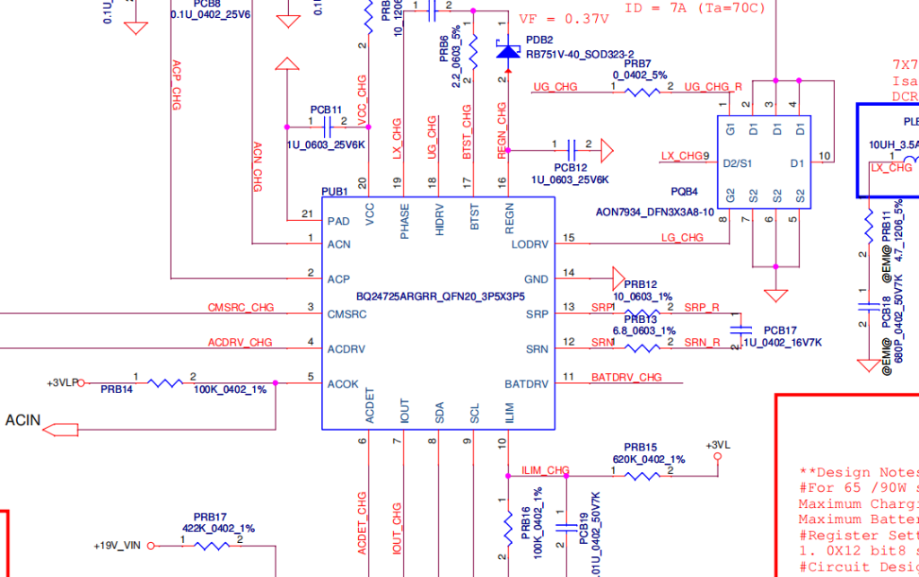
Voltage Checks on Charging IC (7:39-15:26):
Drain Voltage :
The drain of the first MOSFET (PQ202) shows 19.64V.
Gate Voltage (9:02-9:57): The gate of the MOSFET shows very low millivolts (0.01V to 0.183V), indicating that the MOSFET is not switching.
VCC Pin :
The VCC pin (pin 20) of the charging IC receives 19V through a resistor, which is confirmed to be present.
AC Detect Pin (12:31-13:34): Pin 6 (AC Detect) shows 2.6V, indicating the adapter is detected, formed by a voltage divider.
VREG Pin :
Pin 16 (VREG) shows 5.83V and pin 17 also has voltage, which are crucial for the charging IC’s operation.
Diagnosing AC Drive and CM SRC (15:26-18:10): The CM SRC pin (pin 3) and AC Drive pin (pin 4) are critical for driving the gate of the first MOSFET. The video explains that normally, 19V should momentarily appear on CM SRC, which then triggers an internal charge pump in the IC to generate 25-26V on the gate. In this case, both CM SRC and AC Drive show 0V.
Troubleshooting the MOSFET and Charging IC :
Initially, the try removing the resistor connected to the AC Drive pin (pin 4) to see if the charging IC generates the required 25V without the MOSFET connected. It doesn’t, suggesting either a faulty MOSFET or charging IC.
After putting the resistor back, they remove the second MOSFET (PQ203). With the second MOSFET removed, the charging IC successfully generates 25V on the gate of the first MOSFET and 19V on the source, confirming the charging IC is functional.
The Jumper Solution (24:26-31:56): Since the charging IC is good but the MOSFET isn’t switching, the issue lies in the CM SRC line. There is a “shortcut” solution: jumpering 19V directly to the CM SRC line (pin 3). This bypasses the faulty part of the circuit that’s preventing the CM SRC from getting its initial 19V. They emphasize that this should only be done with a clear understanding of the internal logic and no shorts in the output section.
Successful Repair : After placing the jumper, the LED notification on the board lights up, and the laptop successfully powers on and displays an image, confirming the repair. So we highlighted this as a way to save a charging IC when a replacement isn’t available, but reiterates the importance of understanding the underlying logic.
LA-D704P REV 4.0, Model hp-15-bd003tx-BDL50 Schematic Diagram
For educational purpose only download.
For other schematics visit and save the our common schematic page.