• Skip to primary navigation
  • Skip to main content
  • Skip to primary sidebar
  • Skip to footer

DisplayMonk

Solution to your problem

  • Home
    • Privacy Policy
  • About Us
  • Repair Tips
  • Schematics Bios
  • Course
  • Online Jobs
  • Tools
  • Enquiry / Contact
Home » laptop desktop chip level repair help guide » Page 13

laptop desktop chip level repair help guide

Schematic Diagram PDF for ITE

March 13, 2022 by displaymonk

Schematics for ite

Schematics For ITE Free Schematics are given below:

it8702f-a

it8700f

IT8620E-GA-H61M-DS2_R4.0

it8620

it8572

IT8528E

IT8528

IT8527E

IT8518E

IT8518_MK2B

IT8518

IT8518(HX)

IT8517E-datasheet-pdf

it8517e

IT8512EIX-L

I O CHIP LIST

ITE8712

ITE8519E

ITE8502E

ITE8500E

ITE 85021

IT8780F

IT8772E

IT8728F

it8728

it8720F-cxs

IT8720F

IT8720_J_V0.7_Web_121808

it8720

it8718f

it8718

it8712f

IT8705F

IT8705AF

So above are Schematics For ITE Free Schematics.

You can also check our other laptop preparing help guides.

  • Desktop Motherboard Power On But No Display Coming
  • CPU Fan Spins Then Stops Repeatedly
  • PCI Port And KQCPET6 Debug Card
  • The Power Sequence In The Desktop Motherboard
  • Difference Between Intel Core i3 i5 and i7 Processors
  • Components Of The CPU And Identification
  • Guide For Chip Level Repair Dead Desktop Motherboard
  • Desktop Chip Level Repair Guide
  • Desktop SMPS Power Output
  • Types Of Regulated Power Supply Used In Motherboard
  • What Is Computer Architecture
  • Laptop Adapter Charger Repair
  • IC’s In Laptop Motherboard for laptop repair at home
  • Laptop Motherboard Digital Electronics
  • Laptop Motherboard Components List
  • 3 Must Know The Basics Of Laptop Chip Level Repair
  • Laptop Chip Level Repair Career Guide

thank you for your visit…

Filed Under: laptop desktop chip level repair help guide

What Is Multimeter In Laptop Repairing

March 6, 2022 by displaymonk

what is multimeter and how to use it

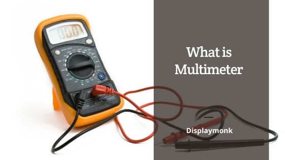
What Is Multimeter And How To Use It:

There are different parts of a multimeter. So we will know what is multimeter in laptop repairing below:

the uses of multimeter
the uses of a multimeter.

1. Power Off :

This is used to turn the multimeter off.

2. DC Voltage :

This is used to set multimeter on DC range. This is helpful to measure DC supply on a multimeter.

3. Probe :

Probes are used to count the voltage supplies. Voltage supplies can be of two types AC voltage or DC voltage. We can measure both types of ac or dc type of voltages using a multimeter.

Just we have to turn on the rotational switch top appropriate location. It can also calculate the beep range and cold testing in laptop reparing.

4. Ohm for resistance :

Ohm is the unit of resistance. We can use the rotary switch in the ohm range. This range measures active available Ohm supply.

5. Buzzer Continuity :

The buzzer is the indicator on the multimeter which can be turned on by the multimeter.  The main purpose of the buzzer is to check continuity via probs.

5. Diode :

The diode range is available on a multimeter. It is used to check any available diode for its value. It can be measured by probes.

6. Temperature :

Temperature can also measure on some multimeters. This feature is if available you can see the temperature symbol on the multimeter which can be targeted via a rotary knob.

7. Rotary Switch :

The main purpose of the rotary switch is to make it unable to measure all things on a multimeter. If we want to measure any range of supply or turn of the multimeter we can use the Rotary switch.

8. DC Current :

The DC current can be measured on a multimeter via the DC range. We have to put one probe on the ground and another probe on the element we want to measure.

9. Display :

The display is used to get information about the current value of the multimeter.  The current can display ac range, dc range, ohm range, buzzer.

You can also check our other laptop preparing help guides.

thank you for your visit…

Filed Under: laptop desktop chip level repair help guide Tagged With: Laptop Motherboard Repair, laptop motherboard repair guide, What Is Multimeter In Laptop Repairing

Component’s Code And Abbreviation On A Laptop Motherboard

February 21, 2022 by displaymonk

Laptop's Component's Codes And Abbreviations

IC stands for the Integrated circuit. There is different ic’s present over laptop motherboard. Each ic has separate functionality. The main purpose of IC is to take the voltage and perform a specific task. Below are component codes and abbreviations on a Laptop motherboard. These are important as you are going to make a career in laptop repairing or you are an experienced repairman.

Motherboard Chips Codes For Component’s Code and Abbreviation On A Laptop Motherboard

In Laptop motherboard chips are very small in size therefore long numbers cannot be printed on the chip. Therefore small codes are printed on the chips. Normally first Two letters indicate the chip number and the last two digits indicate the batch number.

For the chip, we have to check the first two letters only,

Components code and abbreviation on Laptop motherboard

Component Codes And abbreviations For Laptop Motherboard Chips

Chip Code Chip Long Number
A3 RT8209E
A5 RT8100PQV
A8 RT8209M
AA RT8800PQV
AJ RT9607PQV
AO RT8209B
AP RT8800A
AP RT8800APQV
BD RT9605BPQV
A6 RT8209PGQW
CB RT8205D
CJ RT8205A
CK RT8205B
CL RT8205C
CP RT8207
CZ RT8205A
K0 RT8209NGQNGQW
DJ RT8205C
DJ RT8205L
DK RT8204
DS RT8223B
DT RT8205E
DY RT8106GQW
EL RT8015A
EM RT8205L
EQ RT8223M
FF RT8208A
FG RT8208
FG RT8208B
D9 RT9716AGQW
FR RT8204B
GG RT8015B
CZ RT8561AGQW
JL RT8204AGQW
FR RT8204BGQW
H6 RT8204CGQW
CK RT8205BGQW
CL RT8205CGQW
EL RT8015A
CB RT8207LGQW
EN RT8205MGGQW
CP RT8207GQW
DZ RT8113
EF RT8207LGQW
J7 RT8207MGQW
11 RT8223NGQW
JL RT8204A
20 RT8223PZQW
EP RT8223LGQW
EQ RT8223MGQW
FH RT8208B
FF RT8208AGQW
FG RT8208BGQW
H8 RT8208DGQW
C7 RT9293-20
30 RT8208EGQW
31 RT8208BGQW
FH RT8209AGQW
C6 RT8202P
A0 RT8209BGQW
A3 RT8208FGQW
JX RT8209LGQW
DH RT8207L
A8 RT8209MGQW

You can also check for laptop adapter charger repair to repair a charger for a laptop. Also, check for fan spins and stops repeatedly for the desktop CPU also for laptop repairing related fault troubleshooting.

thank you for your visit…

Filed Under: laptop desktop chip level repair help guide Tagged With: Component Codes And abbreviations, Laptop Motherboard Repair, laptop motherboard repair guide

Laptop Motherboard Debug Card

February 20, 2022 by displaymonk

laptop and desktop debug card details

Debug Card – What is debug card and how to use it

Introduction

Debug Card is a powerful diagnostic tool for laptop repair technicians and administrators to troubleshoot
various problems of IBM-compatible PCs. It is easy to install, yet extremely powerful to use. With
Debug Card in hand, you no longer have to go through the tedious and time-consuming process of
trying to figure out what is wrong with your PC hardware. Debug Card will tell you exactly what
is wrong with your PC in just seconds. It saves you time and money.

Our new and improved design of Debug Card diagnostic card can work with almost all popular
types of CPUs, Motherboards, and BIOSes..

System requirements

The Debug card itself only requires an empty PCI or ISA expansion slot. It is not necessary to
install memory chips to perform analysis. “POST Codes” can be displayed through the
hexadecimal display panel on the Debug Card itself.

Debug card indicator

‘Indicators’ are any light-emitting diodes(LED) or hexadecimal display panel that may be
mounted on a Debug Card. This section discusses the following indicators that appear on the
Debug Card:

  • POST-Code Display
  • PCI BUS SIGNALS LEDs

The Diagnostic Code “no”

The Bios diagnostic codes showing “no” indicates that there is no Bios POST code has been received. Same as the initialization codes of the diagnostic card.

PCI Signal Definition:

1.CLK – Motherboard Clock Signal. Should be on when power is supplied to the motherboard even without a CPU.
2. BIOS – BIOS Read Signal. Flashes when the CPU reads BIOS code.
3. IRDY – Device Ready. Flashes when an IRDY signal is detected.
4. OSC – ISA Oscillation Indicator. Indicate ISA Oscillation Signal is available.
5. FRAME – PCI Bus Frame. Should be on under normal circumstances and flashes
when a PCI Frame Signal is detected.
6. RST Reset – After power-on or reset, this indicator should be on for a half-second and then turned off.
7. 12V – Power Supply, 12-Volt Positive. Should be on all the time otherwise, there
is a short circuit.
8. -12V – Power Supply, 12-Volt Negative. Should be on all the time otherwise, there
is a short circuit.
9. 5V – Power Supply, 5-Volt Positive. Should be on all the time otherwise, there is
a short circuit.
10. -5V – Power Supply, 5-Volt Negative. Should be on all the time otherwise, there
is a short circuit.
11. 3V3 – Power Supply, 3.3-Volt. Some motherboards have a 3.3V power supply to
PCI slots. This indicator should be on if the motherboard supplies 3.3V
power.

Installing Debug Card

Installation Procedure

Steps to install a Debug Card:

  1. Install the Debug Card in any available PCI or ISA expansion slot.
  2. Power on the machine

You can see different error codes and their meaning in this article.

Thank you for your visit to CPU Core Section Working For Desktop Motherboards!

You can also check for

Difference Between Intel Core i3 i5 and i7 Processors
Components Of The CPU And Identification With The Full Form Of The CPU
Guide For Chip Level Repair Dead Desktop Motherboard
Desktop Chip Level Repair Guide
Desktop SMPS Power Output
Types Of Regulated Power Supply Used In Motherboard
What Is Computer Architecture
Laptop Adapter Charger Repair
IC’s In Laptop Motherboard for laptop repair at home
Laptop Motherboard Digital Electronics
Laptop Motherboard Components List
3 Must Know The Basics Of Laptop Chip Level Repair
Laptop Chip Level Repair Career Guide on how to be a laptop repairman
Repairing a Dead Laptop
QUANTA Motherboard Identification Number
How To Find a Laptop Motherboard Part Number
Introduction To Chip Level Repair Guide For Laptop
Laptop Battery Charging Section Repair
Laptop Schematics Free PDF

Filed Under: laptop desktop chip level repair help guide Tagged With: Laptop Motherboard Debug Card, Laptop Motherboard Repair

Desktop Motherboard Diagnostic Card

February 20, 2022 by displaymonk

what are signals on debug card

We are going to see some information on Desktop Motherboard Diagnostic Card.

Simple Error LED Light Indicators

  • New simple faults LED lights, show the computer faulty areas, no need to use any
    digital codes interpretation, much easier than the LCD screen diagnostic cards.
  • Tech fact:Due to the periodical updates of the newer bios codes from the Bios
    and/or the computers manufacturers, only the Bios and/or the computer
    manufacturers have the most updated and complete list of the Bios codes. These LED
    lights work just as same as all other diagnostic cards on the market and needs to
    rely on the updated Bios codes, please use these LED codes as a quick reference.
KQCPET6 V6 LED description

KQCPET6 V6 LED Light Descriptions

  • Unstable – If the computer motherboard is not stable, with potential faults, or computer accessories parts are not fully compatible with the motherboard, this LED will be steady ON. (Only PCI and PCIe diagnosis comes with the Stability Test feature) .
  • Stable – The computer is stable, with no error. (Only PCI and PCIe diagnosis comes with the Stability Test feature) .
  • Ready – When this LED light is ON(please take note all 3 dots must light upon the 4digital display, please check the above picture), ok to reboots the computer to do the stability test. If this Ready LED is not On, do not reboot the computer for the Stability Test. (Only PCI, PCIe connections come with the Stability Test feature).
  • -12V – When the test card installing on the standard PCI slot, this LED will be steady ON otherwise, there is no such voltage from PSU or the motherboard is short. When using LPC、PCIE、MINIPCIE、EC、USB connections to test the computer, this LED need not be On.
  • HDD/PCH – Hard Drive / Bridges (North or South) / SATA / USB modules self test failed
  • RUN – This shows the CPU has been running, as soon as the CPU has been initialized and run, this LED will light even though the CPU stopped working now, this LED will remain ON. To check on this LED, remove the CPU, power on the motherboard, if this LED still remains ON,
    the LED needs to be checked for fault.
  • DISP – Video card / integrated motherboard GPU self-test failed.
  • RAM – RAM/motherboard memory module or power fault.
  • CPU – CPU / motherboard CPU coprocessor module or peripheral path self-test failed.
  • IRDY – Improved IRDY LED light, unique LED light when using the PCI slot, this LED lights ON when there is IRDY signal, works the same way as the CLK signal. This LED is absent when using the LPC、PCIE、MINIPCIE、EC connections.
  • FRAME – Improved FRAME LED light, it lights ON when there are frame cycle signals, works the same way as the CLK LED.
  • RST – This LED flashes very quickly for about half a second when using the test card on the PCI slot during the power ON or pressing the Reset button on the computer. It remains ON if the reset wire connects to the wrong other pins on the motherboard or the motherboard reset circuitry is faulty. When using the LPC connection to test the computer, this LED may not light at all, please focus on the digital diagnostic codes. Only connecting with PCI or PCIe, this LED shows the motherboard reset activity.
  • CLK – This LED lights when there is a CLK clock pulse signal. This LED may flash quickly enough so that it looks like never light at all.
  • 12V – This LED should remain steady ON when the test card is installed on the computer PCI slot, otherwise, there is no such voltage from the PSU or the motherboard is shorted. When using the LPC、PCIE、MINIPCIE connections, this 12v LED should remain OFF.
  • AUX3V – This LED is the unique 3.3v indicator on PCI、PCIE slots, should remain ON when the motherboard is powered ON. A few motherboards with built-in PCI slots may not have this voltage. LPC connection does not have this voltage, so this LED will remain OFF.
  • Open codes – Except code ‘no’, when this LED flashes ON and OFF, the codes are the 2digit Qiguan open codes. If this LED remains OFF, the codes are Bios Code. On TypeB cards, this LED steady ON indicates the USB codes.

Precaution for the Diagnostic Card PCI/PCI-E 1X Connection

  • When there are PCI and PCIe connectors on the same motherboard, please
    use the PCI slot.
  • When there is only a PCI-E slot, please install the diagnostic card PCIe
    connector to the motherboard PCI-E X1/X4/X8/X16 connector.
  • Important: Never connect the PCIe connector to the motherboard non
    PCIe (PCI or AGP slots), this may short the diagnostic card and/or
    motherboard when the power is ON.
Precaution for the Diagnostic Card PCI/PCI-E 1X Connection

The Diagnostic Code “no”

The Bios diagnostic codes showing “no” indicates that there is no Bios POST code has been received. Same as the initialization codes of the diagnostic card.

What to do with this Bios Code ‘no’ when the diagnostic card is installed on the PCI slot?

  1. Showing POST code ‘when the diagnostic card is not properly installed on the motherboard.
    solution:Clean the diagnostic card pins by using a paper rubber ②There is dust, rust, or oxidations on the
    motherboard slot. Please clean the slots and reseat the diagnostic card a couple more times. Check the slot pins
    for any loose, bent, or broken pins. All these situations will cause improper contacts so that the diagnostic
    card will not be able to perform the diagnosis or give inaccurate diagnostic results. If there is poor or no
    contact of the pins, the diagnostic card will show the following symptoms: blank display no diagnosis display,
    no Bios Code / wrong code, LEDs remain OFF, normal Qiguan codes will be reported as none.
  2. When CPU never worked, the codes will show ‘no’ and the RUN LED remains OFF
    Solution: Motherboard did not initialize, check if CPU is faulty, check CPU jumpers and settings, check
    PSU voltages, motherboard CMOS battery.
  3. Some empty motherboards without RAM, RAM failed the self-test or RAM incompatibility, the Bios codes
    showing ‘no’.
    Solution: Clean the RAM pins with a paper rubber, clean the RAM slots, reseat the RAM properly. Observe if
    the diagnostic codes are getting the new codes.
  4. The motherboard Bios is faulty
    Solution: Refresh/reprogram the BIOS.
  5. The computer works normally, still showing ‘no’;
    Solution: If still showing ‘no’ after checking all pins contacts are good, the motherboard slot is not getting the BIOS codes, please be advised to use the diagnostic card on the other motherboard slots (LPC/PCI), or on the other motherboards, as soon as any other slot or motherboard gets the different codes than ‘no’, the diagnostic card is a working unit.
  6. Qiguan codes(Only applies to the Qiguan diagnostic card with 4digit Qiguan diagnos is already indicated those factors that causing Bios codes ‘no’.
    Solution: Correct the errors reported by the Qiguan diagnosis codes.

What to do when the codes showing ‘no’ on LPC
connection diagnosis?

  1. First, check on the motherboard LPC connector to make sure it is marked any of the followings:
    LPC_DEBUG, LPC,  DEBUG,  LPC1,  DEBUG PORT,  JLPC,  LPC_CON,  LPC-DEBUG, LPC/TPM1,  JTPM1, TPMS1, TPM, etc. dual rows of the LPC pins;
  2. Next look for the ‘pin1’ on the motherboard LPC debug port.
  3. Double-check the above 2 checks are correct, then select either a large or small LPC connector and align pin 1 to install the LPC connector on the motherboard LPC debug port.
  4. check if the USB power cable is in advance connected to the diagnostic card which will be
    installed on the motherboard LPC debug port.
  5. . Then powers on the computer, if still showing ”no”, motherboard LPC pins could have the
    oxidations or poor contacts, just need to power off and reseat the LPC connectors a few more times
    to help get rids of the oxidations and rust for better pins contacts.
  6. CPU never worked and showing ‘no’ and the diagnostic card RUN LED remains OFF.
    Solution: First check if there is any CPU open circuitry. Check if the CPU is getting the
    power and heating up after powering on.
  7. Some empty motherboards without the RAM installed or the RAM failed the self-test / RAM incompatibility
    will show the code ‘no’, please try using the paper rubber to clean the RAM pins, clean the RAM slots, reseat the
    RAMs and check if there are any new diagnostic codes.
  8. motherboard BIOS faulty.
    solution: refresh or reprogram the Bios and try again. If not familiar with the motherboard BIOS refresh,
    please do not do this.
  9. The computer works normally, still showing ‘no’;                                                                                                            Solution: If still showing ‘no’ after checking all pins contacts are good, the motherboard slot is not
    getting the BIOS codes, please be advised to use the diagnostic card on the other motherboard slots (LPC/PCI), or
    on the other motherboards, as soon as any other slot or motherboard gets the different codes than ‘no’, the diagnostic
    a card is a working unit.
  10. Qiguan codes(Only apply to the Qiguan diagnostic card with 4digit Qiguan diagnosis)already indicated those factors that causing Bios codes ‘no’.
    Solution: Correct the errors reported by the Qiguan diagnosis codes.

What to do when the codes show ‘no’ on PCIe connection diagnosis?

The 2digit codes showing ‘noon the PCIe connection diagnosis indicates that the diagnostic card is not getting the
BIOS Code and not getting the Qiguan 2digit open codes as well.
1. on the motherboards with both PCI and PCIe connectors, please use the PCI as a priority, this is because the
motherboard manufacturers could have designed one of these connectors to output the BIOS codes, while the
other connector will not have the Bios codes.
2. When the motherboard does not come with PCI but PCI-E slot, the diagnostic codes show ‘no’, the followings
are the 2 possibilities.
a. there is other BIOS diagnostic port such as LPC connector on the motherboard. Please use the LPC diagram
guide in this manual to help check if there is LPC debug port on the motherboard, if so, please use the LPC
diagnosis instead.
b. If there is no other LPC debug port but only the PCIe slot, the motherboard has no Bios codes sent to its PCIe
connector, we can do the followings:
①CPU never worked with the bios codes ‘no’ and the RUN LED remains OFF.
Solution: First check if there is any CPU open circuitry. Check if the CPU is getting the power and heating up
after power on.
P.68
②. Some empty motherboards without the RAM installed or the RAM failed the self-test / RAM
incompatibility will show the code ‘no’, please try using the paper rubber to clean the RAM pins,
clean the RAM slots, reseat the RAMs, and check if there are any new diagnostic codes.

③. motherboard BIOS faulty
solution: refresh or reprogram the Bios and try again. If not familiar with the motherboard
BIOS refresh, please do not do this.
④. The computer works normally, still showing ‘no’;
Solution: If still showing ‘no’ after checking all pins contacts are good, the motherboard
the slot is not getting the BIOS codes, please be advised to use the diagnostic card on the other
motherboard slots (LPC/PCI), or on the other motherboards, as soon as any other slot or
motherboard gets the different codes than ‘no’, the diagnostic card is a working unit.
⑤.Qiguan codes(Only applies to the Qiguan diagnostic card with 4digit Qiguan diagnosis)
already indicated those factors that cause Bios codes ‘no’.
Solution: Correct the errors reported by the Qiguan diagnosis codes.


You can also check our other laptop preparing help guides.


thank you for your visit…

Filed Under: laptop diagnostic card, technical category with Uncategorized Tagged With: laptop diagnostic card, Laptop Motherboard Repair

What is Hot Testing vs Cold Testing In Laptop / Mobile

February 20, 2022 by displaymonk

What is Hot Testing vs Cold Testing In Laptop / Mobile

There are major two types of tests commonly used for Laptop Testing and we will also understand what is Hot Testing vs Cold Testing In Laptop or mobile devices.

  1. Hot Test
  2. Cold Test

Hot Testing vs Cold Testing

The first method of Cold Test for laptop preparation consists of testing with a multimeter with keeping the beep mode or diode range on the multimeter.

The second method of Hot Test consists of testing the laptop motherboard by injecting current at its pins. This method used a multimeter dc 20v range to test the voltage. The loss in voltages means a problem with the motherboard. The increase in current is also a symptom of faulty components. The capacitors, diodes, registers, MOSFET’s, ic’s are the most commonly failed components in laptops. Coil mostly do not get problems because they are more durable.

When you complete the hot testing or cold testing you will get some predictions of which components may fail. From these predictions, you can repair that motherboard. The testing should be from start to end within schematics in laptop repairing. Unless you don’t get any defective components to carry out testing for the next flow in schematics.

Advice before starting

It is advisable for newcomers who want to brush up their knowledge in this field to start with cold testing. As being starting with hot testing can burn the component.

As a starter, you don’t want to burn any components. Secondly, the cost of the laptop motherboard components is quite much.

Motherboards you start testing

There are different brands of motherboards you can do this testing. They are

  • acer
  • asus
  • broadwell
  • compal
  • compaq
  • dell
  • H61
  • H81
  • foxcon
  • hp
  • ibm
  • invented
  • lenovo
  • lg
  • quanta
  • samsung
  • sony
  • toshiba
  • wistron
  • x40
  • zenith

You can also check our other laptop preparing help guides.

thank you for your visit…

Filed Under: laptop desktop chip level repair help guide Tagged With: Hot Testing vs Cold Testing, Laptop Motherboard Repair

  • « Go to Previous Page
  • Go to page 1
  • Interim pages omitted …
  • Go to page 11
  • Go to page 12
  • Go to page 13
  • Go to page 14
  • Go to page 15
  • Go to Next Page »

Primary Sidebar

Search On Website

Laptop Desktop Chip Level Help Guide

  • Windows 10 Restarts After Shutdown

    Windows 10 Restarts After Shutdown

    March 24, 2025

  • T.VST59.031 Firmware Software

    T.VST59.031 Firmware Software Download Latest

    March 18, 2025

  • Mobile and Tablet Repairing Institute Class in Ratnagiri, Maharastra

    Mobile and Tablet Repairing Institute Class in Ratnagiri, Maharastra

    December 14, 2024

  • Laptop and Computer Repairing Institute in Ratnagiri, Maharastra

    Laptop and Computer Repairing Institute Class in Ratnagiri, Maharastra

    December 14, 2024

  • pm-modi-lic-sakhi-yojana

    LIC’s Bima Sakhi Yojana 2025: How To Apply?

    December 12, 2024

Footer

Mobile Repair

We do mobile repairing.

Learn more about mobile repairing service.

Laptop Repair

We laptop repairing.

Learn more about laptop repairing service.

TV Repair

We do TV repairing.

Learn more about tv repairing service.

Copyright © 2025 · DisplayMonk

  • Home
  • About Us
  • Repair Tips
  • Schematics Bios
  • Course
  • Online Jobs
  • Tools
  • Enquiry / Contact