First step Check SMPS
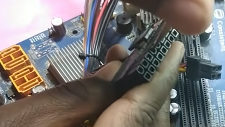
Remove 20 pin connector and 4 pin connector from motherboard.
Secondly, Short the green and black wire with twisser. After doing the short if SMPS starts running that means SMPS is in good working condition.
Second Step
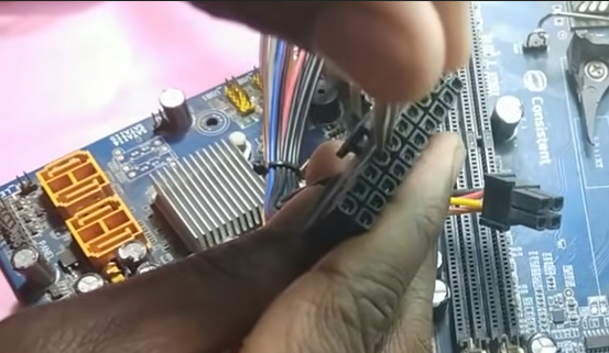
Thirdly, after shorting green and black wire the SMPS fan is not running then check the power cable.
You can check it by keeping the multimeter in the continuity range.
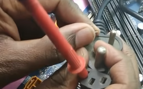
First, put the multimeter point in the first hole of the wire and check for continuity beep sound on the multimeter. The beep sound should come from any
one of the points of the main cable. Then check another hole which should give a continuity beep with the second point. It means the power cable is working fine.
If the beep not coming from any of the points it means the main wire is not working. In that case, we will not change SMPS but change the main wire.
The main cable is shown in the below image as a black thick wire.
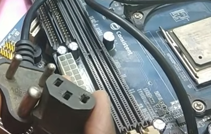
Third step check ATX cable(given in below diagram) for loose

Check connector for loose condition which means is there any loose condition for ATX connector to motherboard is loose.
Fourth step check for jumpers on motherboard.

change jumpers’ position to find out whether the motherboard is starting or not. If the motherboard is not starting change them again to the original position.
Fifth Step Clean the motherboard
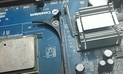
get the motherboard out and clear it with any kind of Thinner which is Isopropyl alcohol / NC Thinner. While cleaning the motherboard use a brush to clean the motherboard. Finally after the cleaning of the motherboard heat the motherboard.
Sixth Step, Cross Checking CPU

Check for the pin of the processor and holes for the processor socket for any dust. Secondly, check for any alternative supported processor as a replacement for the processor and then check.
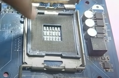
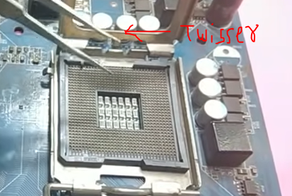
There should be any pin bend in the CPU socket for pinned socket. If found any pin bend then make it straight with the use of twisser.
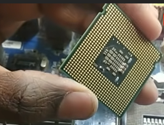
For a pinless processor clean the pins on the processor and then reinsert processor into the motherboard.
Seventh step Check 4 pin ATX connector for any sort condition
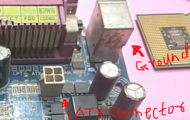
From this 4-pin ATX connector two pins should beep on continuity mode with the ground and two pins should not beep. The hand position with digital multimeter prob should be done in following manner.
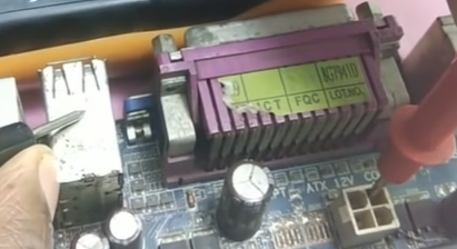
If 4 pins are beeping with Ground it means the problem in the VRM section of the desktop motherboard.
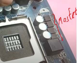
check for any faulty MOSFET found in the above image VRM section.
Eights step By eyes properly check components
scan all motherboard with eyes for any found faulty component. At least use 1 min to check it. Check for burnt track or component/ damaged component.
Ninth step Check for All MOSFETS
No any mosfet should be short , we can check it by using multimeter for the gate and source which should not beep on multimeter on continuity mode.
Tenth step Check port for any fault

remove all the external devices and check if any port is broken. and try to start the motherboard without any external device connected to the port.
Eleventh step Check for component heating
Just plug the main power ATX connector and check for whether any component chip is heating or not. If too much heating then it must be faulty.
Twelths step RTC Crystal Check
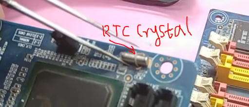
This crystal gets problematic due to many things. Check the required CRO machine but you can do the best way to replace directly it with another board Crystal and check the motherboard.
Thirteenth step Dry sold main IO chip

If upper solutions do not work then use thinner and heat to drysold by removing and refitting the main IO chip in the desktop motherboard. It is also called as power IC.
Last step if everything fails
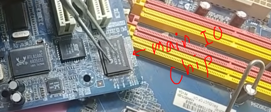
If everything fails change the main IO chip which is also called as power IO chip.
Thank you!
