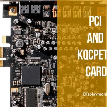
PCI Port And KQCPET6 Debug Card
Firstly the use of PCI Express port is to diagnose desktop motherboards. Secondly, PCI ports come in 4 sizes 1x, 2x, 3x, and 4x. We are going to see PCI Port and Debug Card in detail Signal Names And … Continued

Firstly the use of PCI Express port is to diagnose desktop motherboards. Secondly, PCI ports come in 4 sizes 1x, 2x, 3x, and 4x. We are going to see PCI Port and Debug Card in detail Signal Names And … Continued
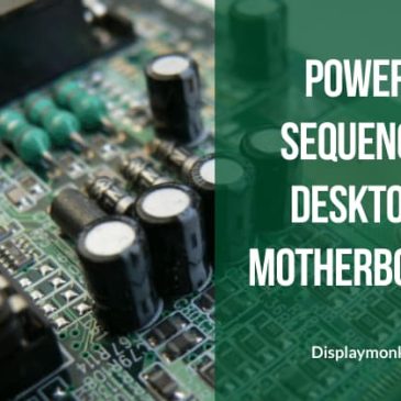
The power sequence in the desktop motherboard is the exchange of signals between the motherboard Chips that takes place before anything appears on the screen. The power sequence is the phase in which the motherboard prepares itself to function. This … Continued
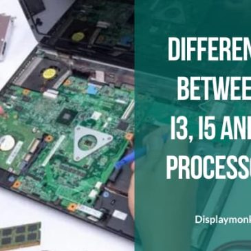
The difference between i3, i5, and i7 is depending on various factors such as cores, caches, and threading. Firstly, we will go for checking for the main difference factors between Intel core i3 i5 and i7 Processors: Cores Number … Continued
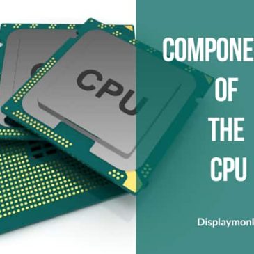
In the below sections, we are going to see the components of the CPU and identification. A Central Processing Unit is a full form of CPU form. It is also called a central processor or main processor. also, It is … Continued

In this section, we will get to have a guide for repair a dead desktop. how to repair a dead desktop? is one of the most asked questions asked by newcomers in the laptop/desktop repair industry. There are different steps … Continued
This section describes a desktop motherboard repair help guide. There are three main components responsible to turn on the motherboard. In the chip level repair guide for desktops, there are given signal names within the motherboard, also their flow is … Continued